2026-02-23
Debugging the DIYRE Colour Duo
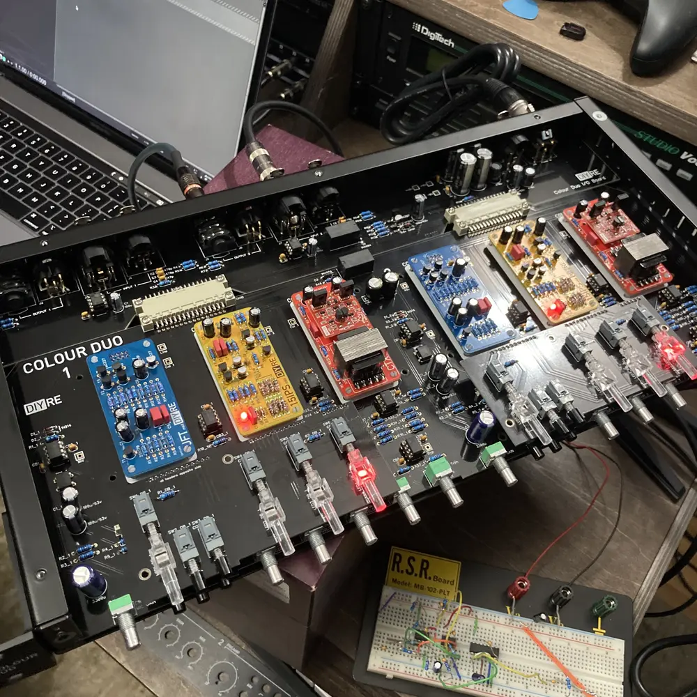
I recently embarked on assembling a DIYRE Colour Duo kit. I knew this was going to be more challenging than anything else I’ve done electrically. I would say this is the first time I’ve really traced a live circuit, so I’m glad it all happened the way it did, even if the problems I encountered weren’t my fault.
The Symptoms
After assembly:
- Power rails were correct (±16V present)
- Signal passed normally in bypass.
- LEDs on Colour modules lit…although questionably.
- With the mix partially dry, I could hear signal.
- Full wet was nearly silent (~–60 dB RMS in my DAW).
- Test point TP4 (Colour 1 output) showed healthy signal (~400 mVAC).
- TP8 (Mix node) showed ~0.
Continuity testing revealed:
- Colour 1 input and output nets were correct.
- Power and ground to the module sockets were correct.
- The signal path from IC2 to IC4 was electrically continuous.
- TP4 → TP8 was open.
This created a contradiction:
Signal existed after Colour 1, but never reached the mix bus.
The Wild Goose Chase
I traced:
- IC2 → IC4
- R11 / trim network
- Daughterboard headers
- Switch routing
- Inter-board connectors
Everything looked correct. Continuity passed everywhere I checked, but nothing was obviously broken. I reflowed joints that looked even slightly off and I reseated the daughterboards a bunch of times, but nothing I did fixed the issue.
The Real Problem
The Colour module sockets were installed exactly as the manual instructed:
“Place sockets on the underside of the PCB.”
And they were. In that configuration though, the pins for the Colour modules couldn’t possibly be fully seated and in turn, made poor contact which caused:
- Power pins still made contact.
- LEDs still lit, but sometimes were the wrong color.
- Signal would partially pass when I pressed down on the module.
The result:
- TP4 had signal.
- The wet bus routing became non-sensical.
- Continuity mostly “worked.”
- Audio never reached the mix node properly.
When I removed and flipped the sockets (against the manual), everything immediately worked.
Lessons Learned
- Trust your gut. If something doesn’t make sense, question the assumptions.
- LEDs lighting does NOT prove correct signal mapping.
- Documentation maybe out of date or wrong.
- Don’t give up.
Outcome
After replacing and correctly (by my estimation) orienting the sockets, the unit passes audio through all three Colour modules.
If you’re building a Colour Duo and experiencing:
- Wet path silence
- TP4 signal but no mix output
- Modules lighting but not passing audio or the colour switches being the wrong color